Archive for March 2nd, 2020
March 2, 2020
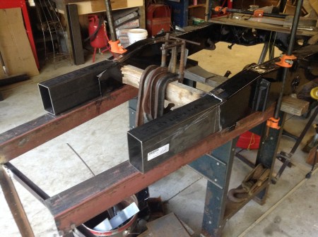
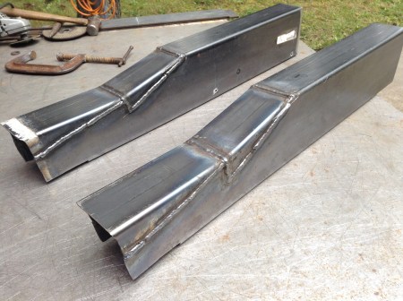
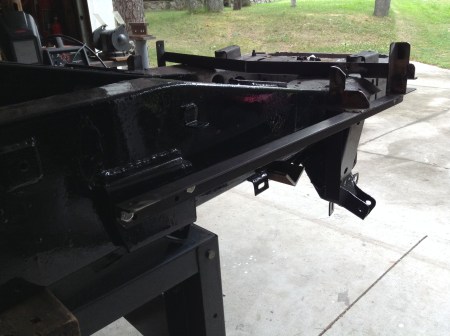
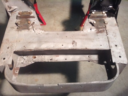
Duplicating the forward chassis was not complicated but was very time consuming. Tight weld joints make for easy, clean work when the welding begins. I worked on this assembly for many, many, many hours:
In the morning I would set a cup of coffee on the assembly and ask “How am I going to do this?” After the day’s work had concluded I ‘d set a cold can of beer on the frame and congratulate myself:
Behold the interlocking rings of Cogitation & Self Congratulation!
Tags:auto restoration, automobiles, autos, British sports cars, cars, classic cars, Frame repair, Jaguar, Jaguar XK, Jaguar XK restoration, jaguar XK120, Jaguar XK140, Jaguar XK150, welding
Posted in Automobile Restoration, British sports cars, Classic Automobiles, Jaguar XK, Jaguar XK 140, Jaguar XK restoration, jaguar XK120, Jaguar XK150 | 3 Comments »
March 2, 2020
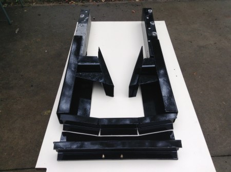
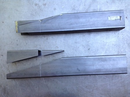
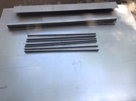
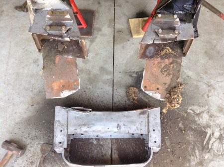
This is the complement of pieces I eventually ended up with. Things did not proceed in a linear fashion. I floundered around quite a bit before the plan came together. Initially I thought I would not need a substantial internal support structure. Ideally a welded joint should be as strong as the metals being joined to one another. After carefully cutting and fitting the joints from the new steel to the existing I realized I couldn’t attain the ideal. I’m a good, certified structural welder but joining the old to the new without some reinforcement would not work.
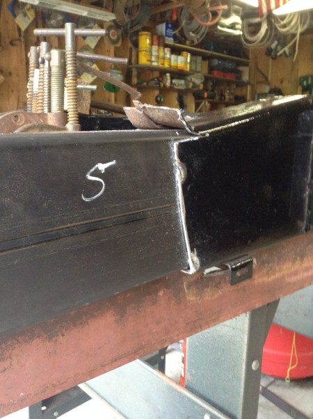
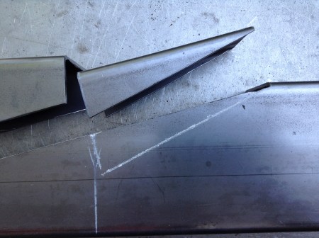
Frame rail step cut
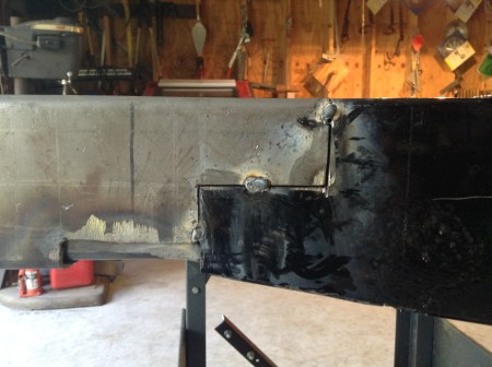
Same joint, frame flipped, new piece tacked in place
The easy fix for a bad joint is called a splice plate. You would weld the joint up, grind it flush and then weld a piece of plate over the joint extending well into both the old and new steel. This is standard practice in steel fabrication. On a restoration of a high value car it wouldn’t fly. I had to contrive some form of interior support.
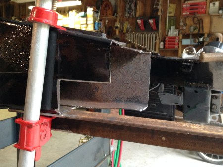
That’s where the 3″ x 5″ rectangular tube came in:
3″ x 5″ tube steel inserted in frame rails
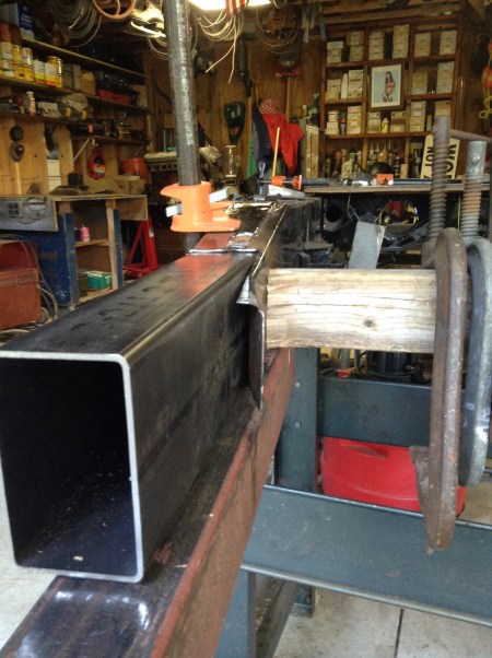
They fit very nicely, snug. I needed to drive them in.
Now they had to be cut down:

Before
After
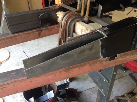
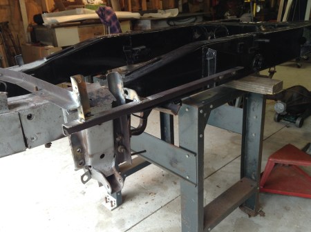
Once the pitch was established I trial fit some of the new assembly:
Things should work out. Now to concentrate on the tube stubs:

Raw tube to desired profile
Step one
After trial fitting a few more dozen times I welded them up:
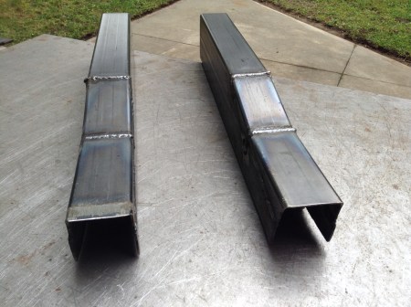
Close enough for iron work.
Tags:auto restoration, automobiles, autos, British sports cars, cars, classic cars, Frame repair, Jaguar, Jaguar XK, Jaguar XK restoration, jaguar XK120, Jaguar XK140, Jaguar XK150, welding
Posted in Automobile Restoration, British sports cars, Classic Automobiles, Jaguar XK, Jaguar XK 140, Jaguar XK restoration, jaguar XK120, Jaguar XK150 | Leave a Comment »
March 2, 2020
There was no point in scabbing in little bits of steel. My location, Southeast Michigan, still has a large amount of smaller steel fabrication shops servicing the auto industry, construction, etc. I walked into Lyndon Fabricators, Redford Michigan, with an idea, a handful of sketches and a pocket of money. They were helpful and happy to take on a small project. They provided me with one 4’x10′ sheet of 18 gauge mild steel (for the fabrication of body panels) and one 5’x10′ sheet of 11 gauge mild steel (.120″). They also sheared and bent pieces according to my sketches. The sketches included duplication of the frame rails at the front of the chassis as well as the rear “extension assembly”. The entire bill came to $540.00.
Sourcing a piece of rectangular tube locally was a little more difficult. If you want to buy a ton of the stuff it’s dirt cheap. If you only want 8′ it’s expensive. I never used to have to buy steel; I was an ironworker before retirement and I could get pretty much whatever I wanted for free. (I built an entire 20’x20′ cabin of scrounged steel, maybe a topic for another blog.)
I couldn’t bum what I needed from former employers and local steel suppliers were too expensive. I found a place, Online Metals, that shipped a piece of 3″ x 5″ x 0.12″, 8′ long to my door for $136.62.
Lyndon did a very accurate job fabricating my pieces and it was now up to me to put it all together.
Tags:auto restoration, automobiles, automotive restoration, autos, British sports cars, cars, classic cars, Frame repair, Jaguar, Jaguar XK, jaguar XK120, Jaguar XK140, Jaguar XK150, welding
Posted in Automobile Restoration, British sports cars, Classic Automobiles, Jaguar XK, Jaguar XK 140 | Leave a Comment »
March 2, 2020
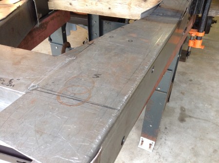
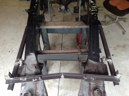
I had to regroup. I clamped and tack welded the forward cross member back in place. I had previously tack welded a piece of angle iron from rail to rail to prevent the frame from springing either in or out once the forward cross member was cut loose. Then I strung a center line with masons string.
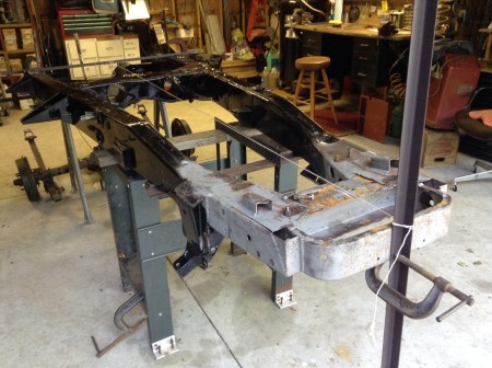
At intervals along the length of the frame I measured overall rail to rail dimensions as well as rail to center line and noted them on a diagram. There were differences up to 3/8″ which I attributed to a prior impact to the right front. I compared them with dimensions as given in Bernard Viart’s Jaguar XK140 Explored. (Anyone undertaking a restoration of a 140 will find this book very helpful. Don’t let yourself get ripped off though, there are copies on eBay advertised for $1,000. +! I was able to get mine through Welsh Jaguar for $225. in 2016. Still expensive but invaluable.)
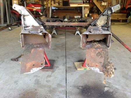
In order to relocate the shock towers accurately I fabricated a pair of jigs from light 1″ angle iron.
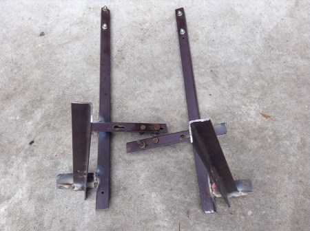

I attached them with bolts to an area of the rails that would not be replaced, i.e., the master cylinder brackets.
I attached the front to mounting holes in the shock towers themselves and drilled holes to relocate the lower wishbone control arms.

Once this information was recorded I was free to commence cutting the frame apart.
Tags:automotive restoration, British sports cars, classic cars, Frame repair, Jaguar XK, Jaguar XK140, layout, welding
Posted in Automobile Restoration, British sports cars, Classic Automobiles, Jaguar XK, Jaguar XK 140 | Leave a Comment »
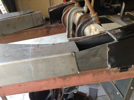
March 2, 2020
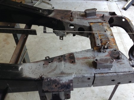
 Maybe I could get away by just replacing the forward cross member. If I could pop it loose, leave the frame rails and steering rack mounts, that might do it:
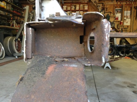
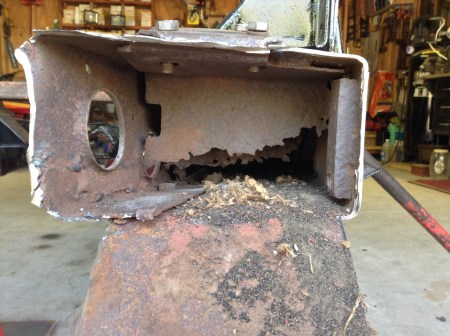
Ouch. This project would both add years to my life and take them off…
Tags:auto restoration, automobiles, automotive restoration, autos, cars, classic cars, Frame repair, Jaguar, Jaguar XK, Jaguar XK140, welding
Posted in Automobile Restoration, British sports cars, Classic Automobiles, Jaguar XK, Jaguar XK 140 | Leave a Comment »


You must be logged in to post a comment.