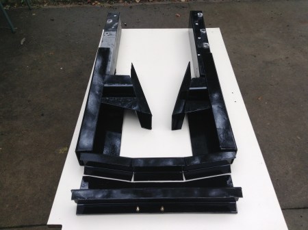
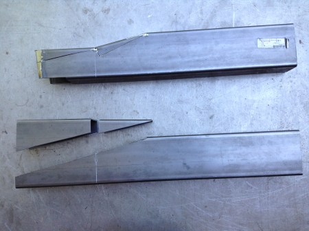
This is the complement of pieces I eventually ended up with. Things did not proceed in a linear fashion. I floundered around quite a bit before the plan came together. Initially I thought I would not need a substantial internal support structure. Ideally a welded joint should be as strong as the metals being joined to one another. After carefully cutting and fitting the joints from the new steel to the existing I realized I couldn’t attain the ideal. I’m a good, certified structural welder but joining the old to the new without some reinforcement would not work.
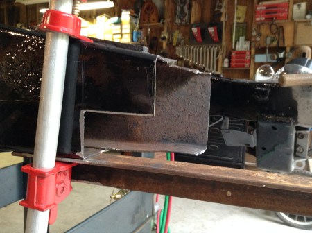
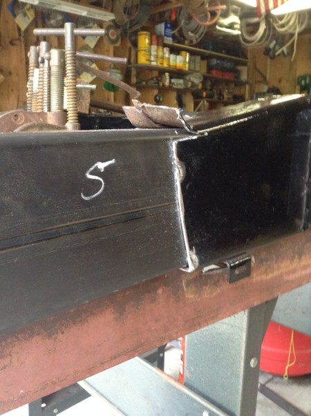
Frame rail step cut
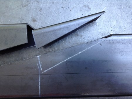
Same joint, frame flipped, new piece tacked in place
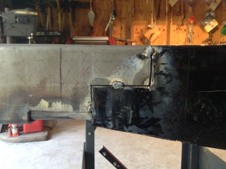
The easy fix for a bad joint is called a splice plate. You would weld the joint up, grind it flush and then weld a piece of plate over the joint extending well into both the old and new steel. This is standard practice in steel fabrication. On a restoration of a high value car it wouldn’t fly. I had to contrive some form of interior support.
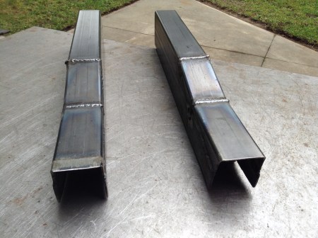
That’s where the 3″ x 5″ rectangular tube came in:
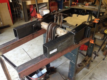
3″ x 5″ tube steel inserted in frame rails
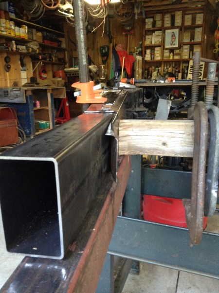
They fit very nicely, snug. I needed to drive them in.
Now they had to be cut down:

Before
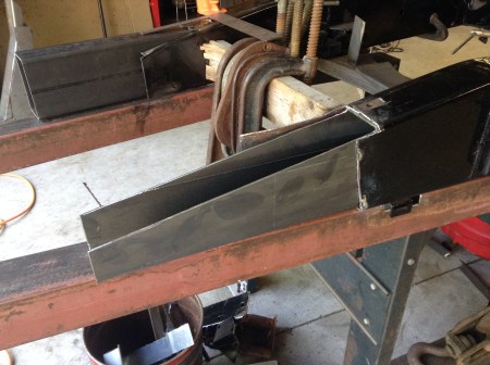
After
Once the pitch was established I trial fit some of the new assembly:
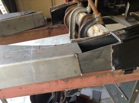
Things should work out. Now to concentrate on the tube stubs:

Raw tube to desired profile
Step one


After trial fitting a few more dozen times I welded them up:
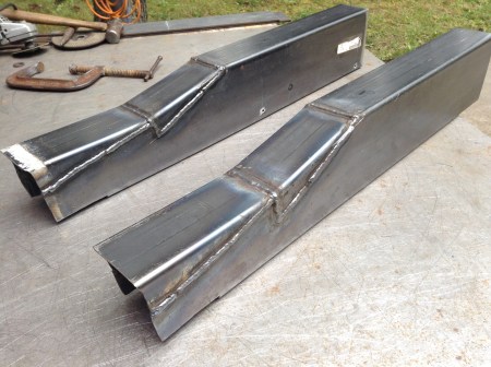
Close enough for iron work.
Tags: auto restoration, automobiles, autos, British sports cars, cars, classic cars, Frame repair, Jaguar, Jaguar XK, Jaguar XK restoration, jaguar XK120, Jaguar XK140, Jaguar XK150, welding

Leave a comment